Mastering GD&T Drawings: A Comprehensive Guide
Understanding Geometric Dimensioning and Tolerancing (GD&T) is essential for engineers, machinists, inspectors, and anyone involved in the manufacturing process. GD&T provides a standardized language to describe the geometry and allowable variation of parts and assemblies. This guide will walk you through a step-by-step approach to reading GD&T drawings, enriched with insights from GD&T expert R. Dean Odell.
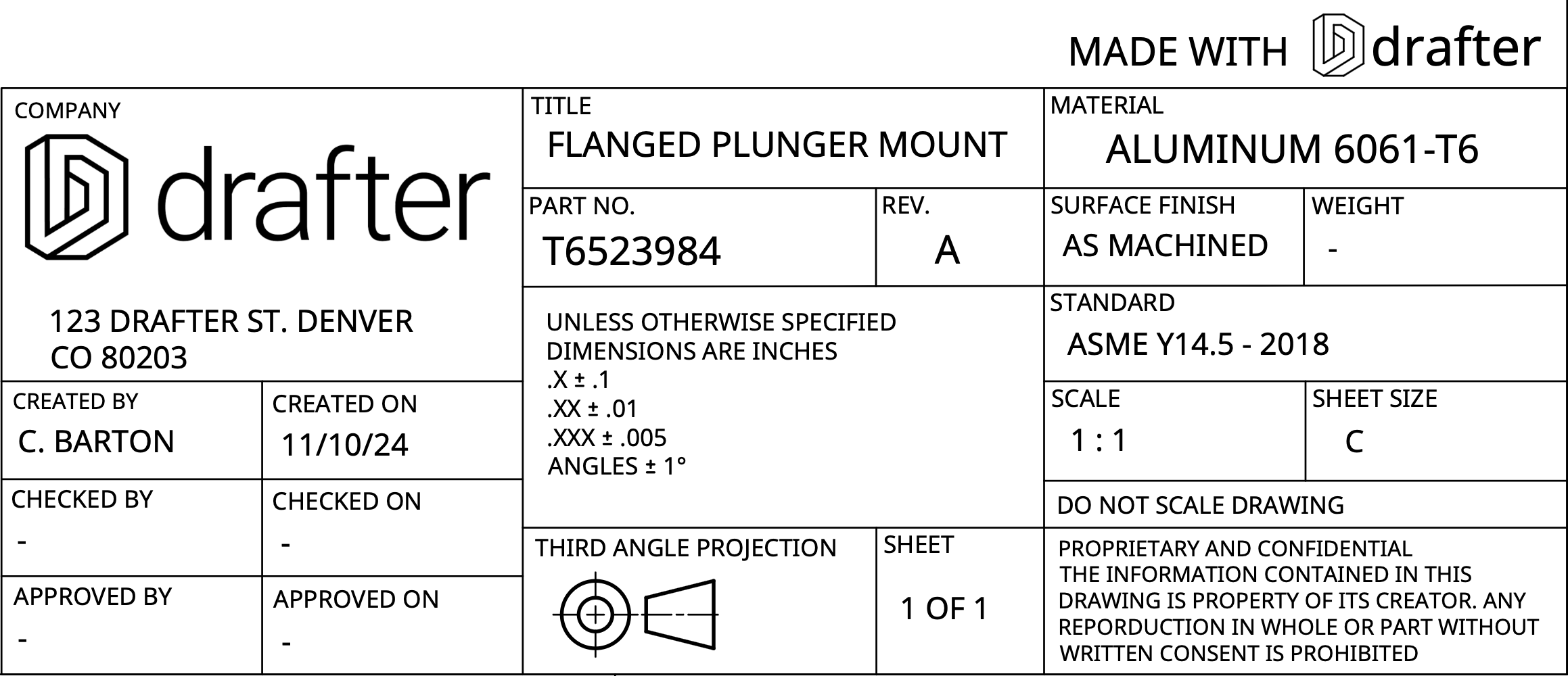
1. Start with the Title Block
The title block is the starting point for interpreting any engineering drawing. It contains crucial information about the part or assembly.
- Check the Origin and Legitimacy: Ensure you’re working with the correct and most recent version of the drawing.
- Verify Revision Levels: Confirm that the revision level matches the latest approved version to avoid working with outdated information.
- Look for Approval Status: Determine if the drawing is approved for production or if it’s a preliminary or study drawing.
2. Review the General Notes
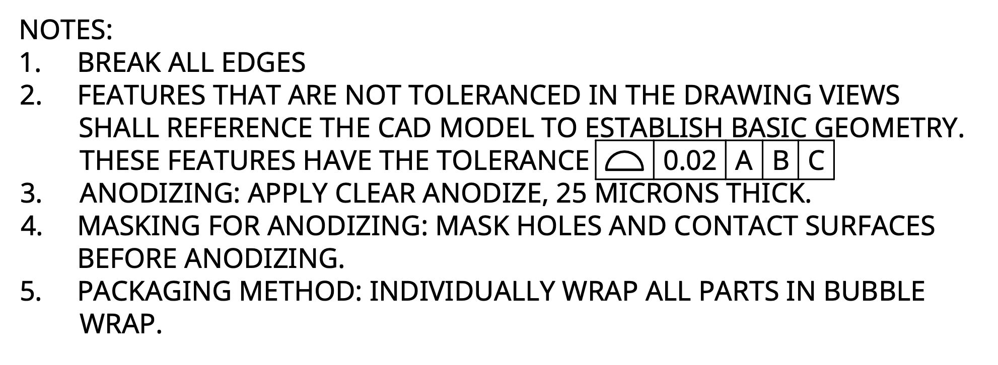
Before diving into the details, read the general notes section, which can contain important information affecting the interpretation of the drawing.
- Identify Special Instructions: Notes may include surface finish requirements, painting or coating instructions, welding specifications, or other essential details.
“Before looking at all the views, it’s always important to look at the notes first... The general notes have things that are going to make the part easier to deal with or more difficult to deal with.” — R. Dean Odell
- Consider Manufacturing Implications: General notes might specify processes that impact how the part should be made or inspected.
3. Understand the Views and Dimensions
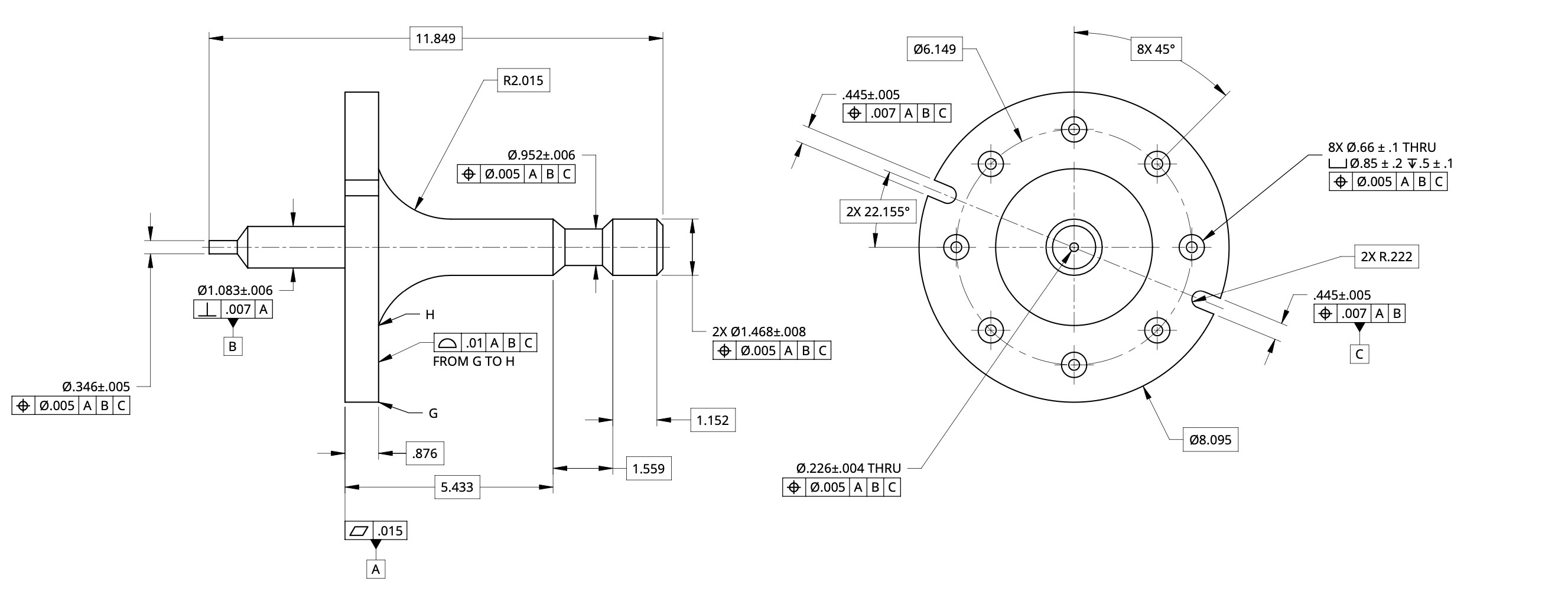
Examine all the views provided to get a comprehensive understanding of the part’s geometry.
- Visualize the Part: Use the front, side, top, and isometric views to mentally construct the 3D shape of the part.
- Check Dimensions for Scale: Look at key dimensions to understand the size and scale of the part.
- Tip: Identifying a major dimension (e.g., overall length or width) helps in visualizing the part’s actual size.
4. Identify Datum Features
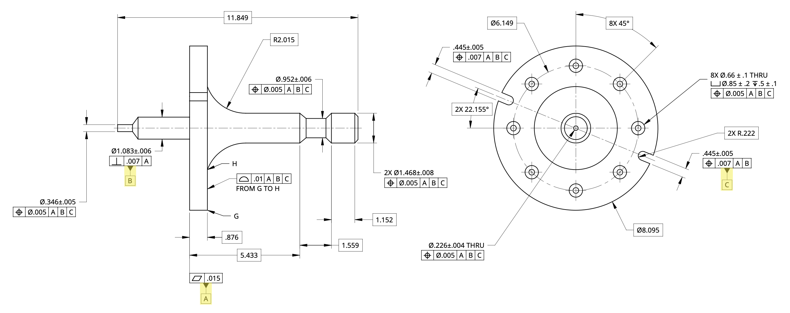
Datums are reference points, lines, or surfaces that exist in theory, but can be derived from physical portions on the part indicated as datum features. These datum form a datum reference frames, from which measurements originate from.
- Highlight Datum Features: Mark all datum feature symbols (e.g., A, B, C) on the drawing.
“I always tell people, if you can, go through with highlighters and highlight all the datum feature symbols.” — R. Dean Odell
- Associate Datums with Features: Understand what physical feature each datum refers to (e.g., a surface, cylinder, or width.)
5. Analyze Feature Control Frames
Feature control frames specify the geometric tolerances applied to features concerning the datums
- Examine Datum References: Note which datums are referenced and the order in which they appear.
- Break Down Each Frame: Understand the type of geometric control (e.g., position, profile, flatness) and the tolerance specified.
6. Determine Material Conditions
Material conditions affect how tolerances are applied based on the size of the feature.
- Identify MMC, LMC, or RFS:
- MMC (Maximum Material Condition): Tolerance applies only at the MMC size, “bonus” tolerance may be available.
- LMC (Least Material Condition): Tolerance applies only at the LMC size, “bonus” tolerance may be available.
- RFS (Regardless of Feature Size): Tolerance applies regardless of the feature’s actual size.

- Understand Inspection Implications: Take note of how material condition boundaries influence the part; these will be measured and accepted during inspection.
7. Consider the Manufacturing Process
Knowing the intended manufacturing process can impact how you interpret the drawing and plan for production.
- Identify the Process: Determine if the part is to be machined, welded, forged, cast, or made from sheet metal.
“What is the main manufacturing process? Machined? Welded? Forged/cast? Sheet metal?” — R. Dean Odell
- Assess Feasibility: Some features may be challenging or impossible to produce with certain processes, requiring design adjustments.
8. Evaluate Tolerances and Feasibility
Assess whether the specified tolerances are practical and achievable with the intended manufacturing process.
- Check for Reasonable Tolerances: Extremely tight tolerances may require specialized equipment or processes, increasing cost and production time.
- Identify Potential Issues: Look for features that may pose manufacturing challenges, such as very thin walls or deep holes.

9. Look for Potential Errors or Ambiguities
Even well-prepared drawings can contain mistakes or unclear instructions.
- Verify Consistency: Ensure that dimensions and tolerances are consistent throughout the drawing.
- Seek Clarification if Needed: If something doesn’t make sense, consult with the designer or engineer, (if possible), to avoid misunderstandings.
- Seek Consensus. If a drawing has a clear error, and it can not be resolved by contacting the design activity, review the error with the relevant internal stakeholders and establish how you will interpret that error.
10. Understand Different Perspectives
Recognize that various professionals may interpret the drawing differently based on their roles.
- Designers: Focus on functionality and compliance with standards.
- Machinists: Concerned with manufacturability and practical aspects of producing the part.
- Inspectors: Emphasize measurement and verification of tolerances.


