
Learn with Drafter
GD&T, drawings, and how parts get made.
To read the GD&T guides in order, follow the GD&T path .
- Articles
- 16
- GD&T
- 11
- Engineering Guide
- 3
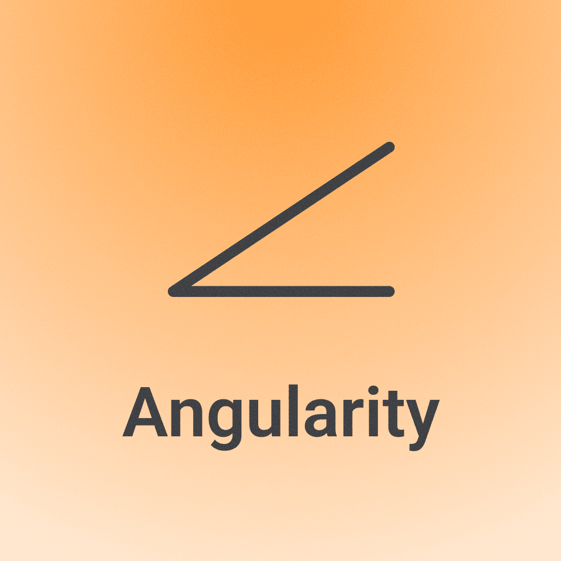
Angularity
Angularity in GD&T is a symbol that defines the orientation of one feature relative to another at a specified angle within a 3D tolerance zone.Surface control shown to left. Angularity can also apply to a FOS where the derived median plane or line is controlled.
 / GD&T
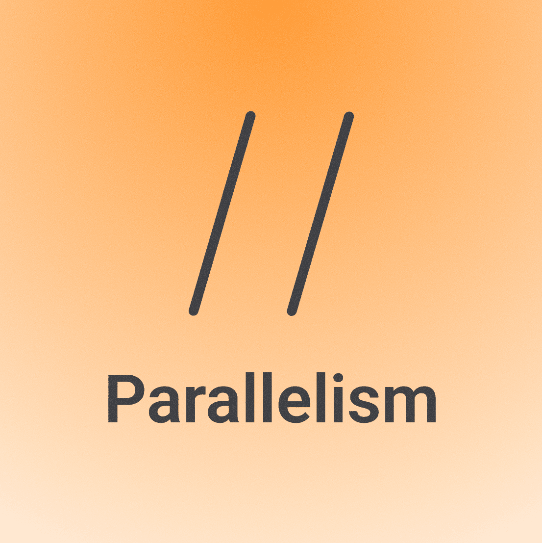
Parallelism
Parallelism in GD&T ensures that a referenced feature maintains a parallel orientation to a specified datum surface or line within a 3D tolerance zone.
 / Engineering Guide
Master the Basics of DFM (& finally show your machinist some love)
A practical guide to designing parts that are easy to manufacture and cost-efficient at scale. Learn how to reduce production headaches, avoid expensive mistakes, and earn the respect of your machinist.
 / Engineering Guide
Why your tolerance stack-up keeps failing & FREE spreadsheet to fix it
You thought you were just dimensioning a hole. Next thing you know, you’re knee-deep in Excel, running trig functions, trying to figure out why the assembled part is 0.4 mm out of alignment. Welcome to tolerance stack-ups.
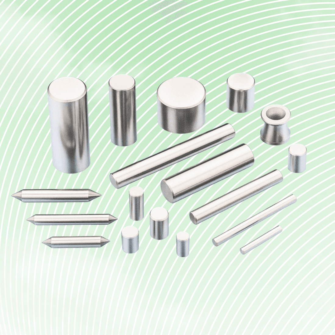
Why Your Dowel Pin Doesn’t Fit, and How to Fix It
Understanding how parts actually fit, clearance, interference, transition, and why “H7/g6” isn’t just a weird robot code.
 / GD&T
Straightness
Straightness is one of the most fundamental form tolerances. It is used to ensure that a feature, such as a surface or an axis, conforms to a specific linear path without deviations. Straightness is crucial for parts where linear precision is vital for fit, function, and performance.
 / GD&T
Runout
Runout is a crucial concept that helps engineers control the functional relationship of features during rotation. Runout tolerances are applied to features that revolve around an axis, such as shafts, cylinders, and disks, to ensure that these components operate smoothly without excessive vibration or wear.
 / GD&T
Basic Dimensions
Basic dimensions serve as the bedrock for communicating design intent with clarity and precision. These dimensions, enclosed in a rectangular box on engineering drawings, are critical for defining the exact geometry of features in relation to datums and tolerances. This article will delve into the purpose, application, and importance of basic dimensions in mechanical design.
 / GD&T
Position
In the world of mechanical engineering and manufacturing, Geometric Dimensioning and Tolerancing (GD&T) is a cornerstone for ensuring that parts meet design intent and function properly. Among the most critical concepts in GD&T is position. This article unpacks what position is, why it matters, and how to interpret and apply it effectively in your designs.
How to Read a GD&T Drawing: Insights from R. Dean Odell
Understanding Geometric Dimensioning and Tolerancing (GD&T) drawings is essential for anyone involved in the design, manufacturing, or inspection of parts. These drawings are the language of engineering, conveying complex geometrical requirements that ensure parts fit and function correctly. But for many, interpreting GD&T can be a daunting task. To demystify the process, we sat down with GD&T expert R. Dean Odell, who shared his step-by-step approach to reading these intricate drawings. Through his insights and experiences, we’ll explore not just the how, but the why behind each step, making the journey engaging and informative.
 / GD&T
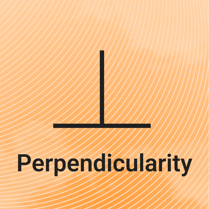
Perpendicularity
Perpendicularity ensures that surfaces and features are aligned perfectly at 90 degrees to each other, which is vital for the proper functioning of assembled parts. While the concept might seem straightforward, the impact of perpendicularity on the performance, assembly, and longevity of parts is profound. Let’s explore what GD&T perpendicularity is, why it matters, and how to use it effectively in your engineering drawings.
 / GD&T
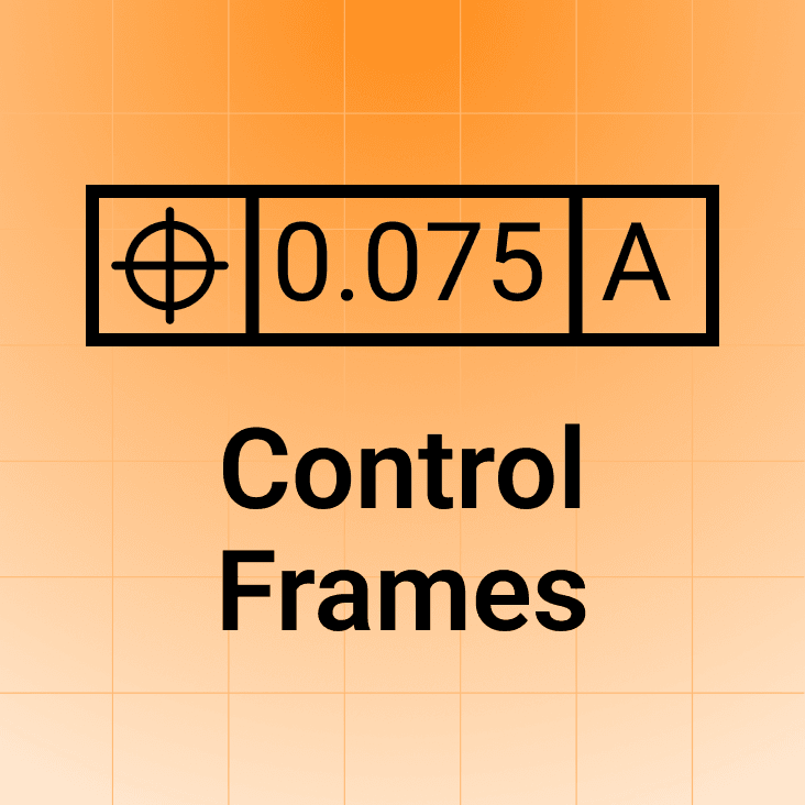
Feature Control Frames
The essential tool for specifying tolerances on part features is the Feature Control Frame. Whether you’re designing a critical aerospace component or a simple bracket, the feature control frame allows you to communicate how a feature should be measured and what its limits are in terms of form, orientation, location, and more. In this article, we’ll dive into what feature control frames are, why they’re vital for your engineering drawings, and how to apply them effectively.
 / GD&T
Datums
Datums are a fundamental aspect of Geometric Dimensioning and Tolerancing (GD&T), serving as the foundation for defining how parts are measured, controlled, and assembled. In this guide, we’ll cover what datums are, how to choose them, how they influence part movement by controlling Degrees of Freedom (DOF), how they are used in inspection, and why they are critical for ensuring your part functions within its intended Design Intent.
 / Engineering Guide
The GD&T Guide: Everything you need to create professional drawings
Cease the endless scroll across the internet looking for examples on how to call things out or understand what each of your decisions mean when you make a drawing. This article will help you understand the basics of what things mean, how to interpret them, and how to clearly communicate your Design Intent on your own drawings.
 / GD&T
Profile
Profile is a versatile and powerful tool for defining the exact shape, size, and location of a surface. While it may sound complex, understanding GD&T profile is crucial for ensuring that your parts not only fit together but also perform exactly as intended. Let’s explore what GD&T profile is, why it’s important, and how to use it effectively in your engineering drawings.
 / GD&T
Flatness
Flatness is a fundamental form control that ensures surfaces are even and functional. Flatness might seem simple, but it’s crucial in making sure your parts fit together and perform as intended. Let’s explore what GD&T flatness is, why it matters, and how to use it effectively in your engineering drawings.