What Exactly is GD&T Profile?

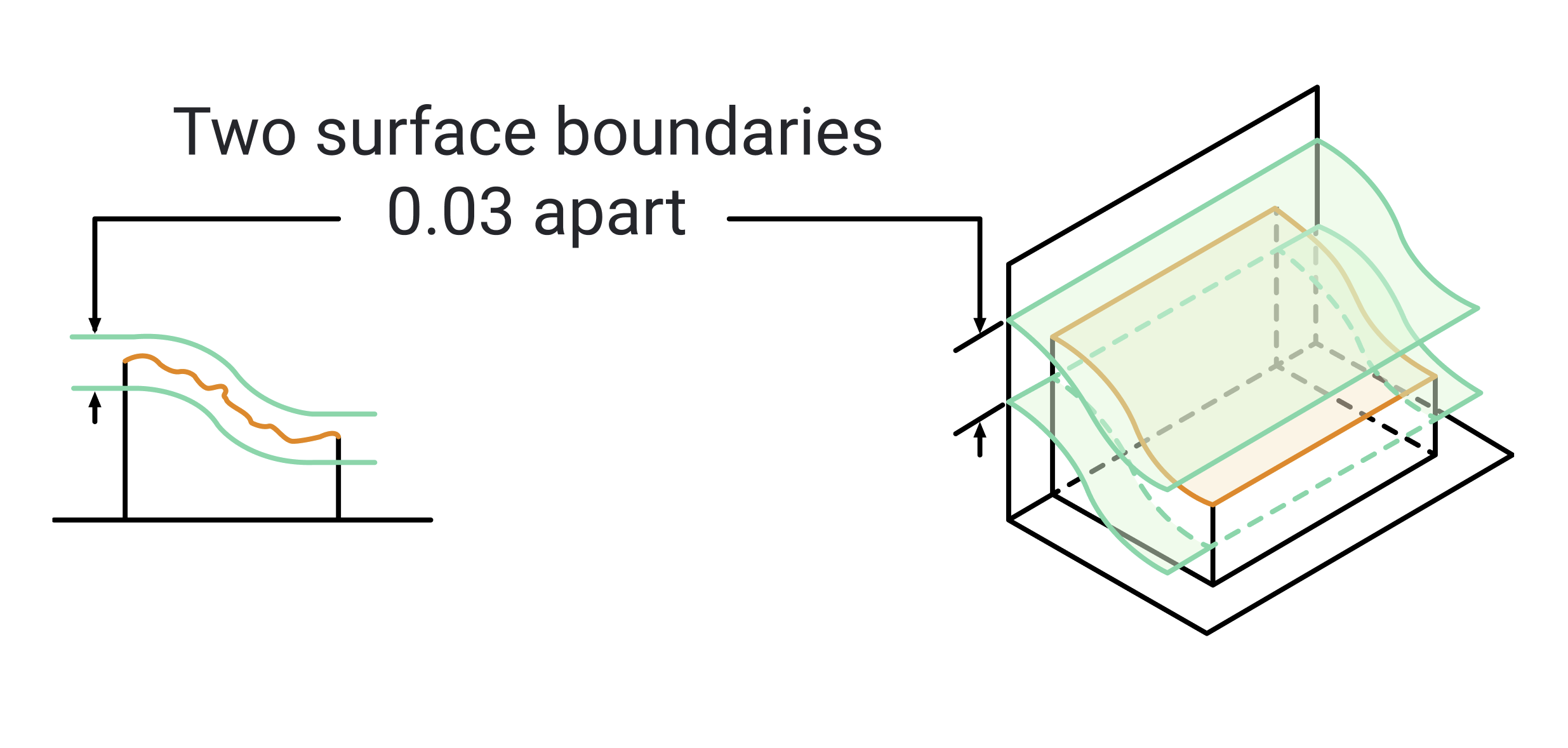
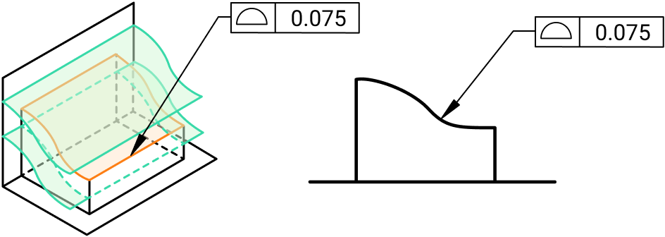
In GD&T, the profile is a three-dimensional tolerance that controls the form, orientation, size, and sometimes location of a surface. Essentially, it defines a tolerance zone around a surface, within which the entire surface must lie. This tolerance zone can be either bilateral (equally distributed on both sides of the nominal surface) or unilateral (only on one side of the nominal surface), depending on the specific requirements of your part.
Unlike other form controls such as flatness or straightness, which deal with simple, linear features, the profile is used to control more complex surfaces. Whether you’re dealing with curves, freeform surfaces, or intricate shapes, the profile is the go-to tool for ensuring that your parts maintain the desired geometry throughout the manufacturing process.
The Importance of Profile in Engineering
Imagine designing a part with a complex curved surface that must mate precisely with another component. Any deviation from the intended shape could lead to gaps, misalignment, or even complete functional failure. That’s where GD&T profile comes into play—it ensures that your part’s surface follows the exact contour you’ve designed, within the specified tolerance.
In industries like aerospace, automotive, and medical devices, where precision and reliability are paramount, controlling the profile of a surface is critical. Even small deviations can lead to issues like uneven stress distribution, premature wear, or interference with other parts. By specifying a profile tolerance, you ensure that the surface geometry meets the design intent, leading to better performance, longer part life, and fewer manufacturing errors.
Applying GD&T Profile in Engineering Drawings


When it comes to applying profile tolerances in your engineering drawings, clarity and precision are key. Here’s how to do it effectively:
- Defining the Profile Tolerance Zone: The first step is to determine whether your profile tolerance will be bilateral or unilateral. In a bilateral tolerance, the tolerance zone is equally distributed on both sides of the nominal surface. In a unilateral tolerance, the zone is only on one side of the surface. The choice between these two depends on the specific functional requirements of your part.
- Bilateral Tolerance: This is the most common type of profile tolerance. It provides a balanced tolerance zone, allowing the surface to deviate slightly from the nominal in both directions. This is ideal for surfaces where symmetry is important or where minor deviations on either side won’t impact functionality.
- Unilateral Tolerance: This is used when deviations in one direction could be more problematic than in the other. For example, if a surface needs to fit snugly against another part on one side but has some leeway on the other, a unilateral profile tolerance would be appropriate.
- Using the Feature Control Frame: Just like with flatness, the profile tolerance is specified in a feature control frame in your drawing. This frame includes the profile symbol, the tolerance value, and any applicable datum references. It’s essential to carefully choose the datum references, as they establish the orientation and location of the tolerance zone relative to other features.
- Datum References: In many cases, the profile tolerance will be related to a set of datums, which are the references for the entire part. These datums provide the necessary orientation and location, ensuring that the surface is controlled not just in its form, but also in its position relative to other critical features.
- Composite Profile Tolerances: In some cases, you may need to control both the form and the location of a surface with a single tolerance. This is where composite profile tolerances come in. A composite tolerance allows you to specify a tighter tolerance zone for the surface’s form while allowing a looser tolerance for its location.
- Application of Composite Tolerances: This approach is particularly useful for parts that require high precision in the surface shape but can tolerate more variation in their location. By using a composite tolerance, you can ensure that the surface remains within the required form tolerance while allowing for some flexibility in positioning, simplifying manufacturing without compromising on function.
How to Measure Profile Tolerance
Measuring the profile of a surface requires precise tools and methods. Here are the most common techniques:
- Coordinate Measuring Machines (CMM): CMMs are widely used for measuring profile tolerances. These machines use probes to collect data points on the surface, which are then compared to the nominal profile. CMMs provide accurate, detailed measurements, making them ideal for complex surfaces.
- Data Analysis: The CMM collects a cloud of points on the surface, which are then analyzed to determine how closely the actual surface matches the nominal design. The deviations are plotted, and the surface is checked to ensure it remains within the defined tolerance zone.
- Optical Scanning and Laser Scanning: These non-contact methods are particularly useful for complex surfaces that are difficult to measure with traditional contact methods. Optical scanners or laser scanners create a 3D model of the surface, which can then be analyzed for profile deviations.
- Advantages: Non-contact methods are ideal for delicate surfaces or those with intricate details that might be damaged or missed by a contact probe. They also allow for rapid measurement of large areas, making them efficient for production environments.
- Comparators and Templates: For simpler profiles or less critical applications, comparators or custom templates can be used. These tools compare the surface to a known standard, providing a quick and straightforward way to check profile conformance.
- Limitations: While effective for certain applications, these methods are less precise than CMMs or optical scanning and are generally used for preliminary checks or lower tolerance requirements.
Challenges in Controlling Profile
Controlling profile tolerances comes with its own set of challenges. Here are a few key considerations:
- Complex Geometry: The more complex the surface, the more difficult it can be to control the profile. Surfaces with curves, bends, or intricate shapes require careful consideration of how the profile tolerance will be applied and measured.
- Best Practices: When dealing with complex geometries, it’s crucial to work closely with your manufacturing team to understand the limitations of your processes and to ensure that the tolerance specified can be achieved consistently.
- Material Variability: Different materials can behave differently during manufacturing, affecting the profile of a surface. For example, softer materials may deform more easily, while harder materials may be more difficult to machine to the desired profile.
- Material Considerations: When specifying a profile tolerance, consider the material properties and how they might affect the final shape. Adjust your tolerance values accordingly to account for material-specific behaviors.
- Manufacturing Process Control: Processes like machining, casting, or 3D printing can introduce variations that affect the profile of a surface. Implementing strict process controls and monitoring is essential to maintain the required profile tolerance.
- Process Optimization: Work with your manufacturing team to identify potential sources of variation and to optimize processes to reduce these variations. Regular calibration of equipment and adherence to best practices are essential for achieving consistent profile control.
Summary
- GD&T Profile: A versatile tolerance that controls the form, orientation, size, and location of a surface, ensuring it lies within a specified tolerance zone.
- Importance: Critical for ensuring that complex surfaces maintain their designed shape, fit, and function, particularly in high-precision industries.
- Measurement Methods:
- Coordinate Measuring Machines (CMM): High precision, ideal for complex surfaces.
- Optical Scanning and Laser Scanning: Non-contact, suitable for delicate or intricate surfaces.
- Comparators and Templates: Simple, effective for basic profiles or less critical applications.
- Application in Drawings:
- Define the profile tolerance zone (bilateral or unilateral).
- Use a feature control frame to specify profile tolerance, including datum references if necessary.
- Consider composite profile tolerances for controlling form and location.
- Challenges:
- Complex Geometry: Requires careful consideration of tolerance application and measurement.
- Material Variability: Material properties can affect profile; adjust tolerances accordingly.
- Manufacturing Process Control: Implement strict controls to maintain profile tolerance.
- Best Practices:
- Collaborate with manufacturing teams to ensure tolerance feasibility.
- Optimize processes and regularly calibrate measurement tools.
- Educate teams on the importance of profile tolerance and its measurement.


