What Exactly is GD&T Perpendicularity?

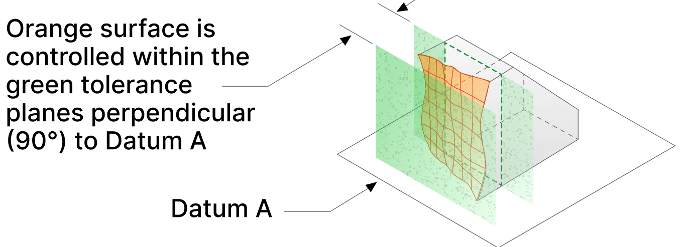
Perpendicularity in GD&T refers to the condition where a feature, such as a surface, axis or feature of size, is exactly 90 degrees relative to a datum plane, axis or feature of size. It is defined by a tolerance zone within which the feature must remain within a tolerance zone that is perpendicular to the datum. This zone is usually a cylinder or two parallel planes, depending on whether the feature is a surface. Or feature of size
Perpendicularity is a crucial orientation control, ensuring that parts are correctly aligned during assembly. Unlike flatness or straightness, which deal with only with form, perpendicularity deals with the orientation of one feature relative to another, while also controlling form when applied to a surface This makes it essential for parts that must interface accurately, such as holes that need to be perfectly aligned for bolts or mating surfaces that must meet at exact angles.
All 90-degree angles on a drawing come with an associated tolerance. If GD&T (Geometric Dimensioning and Tolerancing) perpendicularity is not applied, the angular tolerance defaults to the general tolerance notes, which often specify a tolerance of plus or minus one degree or less. In practice, measuring such precise angles is challenging, and there is no universally accepted method for determining the exact angular value of a surface.
When GD&T perpendicularity is applied, it designates the 90-degree angle as a “basic” dimension, meaning it is theoretically exact and does not require measurement within the general angular tolerance. Instead, the perpendicularity tolerance defines the allowable deviation from perfect perpendicularity. This tolerance is typically more generous and is accompanied by an agreed-upon system for interpretation and measurement, making it more practical to apply and verify in manufacturing processes.
Instead of measuring the angle on the surface relative to an unspecified feature, the tolerance is measured by determining whether the surface is in a tolerance zone relative to a specified datum.
The Importance of Perpendicularity
Imagine trying to assemble a structure where the holes for bolts don’t align perfectly, or where the surfaces meant to be at right angles are slightly off. The result? Misalignment, improper load distribution, and potential part failure. Perpendicularity ensures that parts come together as designed, without gaps or misalignments that could compromise the integrity of the assembly.
In industries such as aerospace, automotive, and precision machinery, perpendicularity is not just a requirement—it’s a necessity. Proper perpendicularity ensures that forces and loads are distributed evenly across a structure, reducing the risk of stress concentrations and improving the overall durability and performance of the product. A small deviation in perpendicularity can lead to significant issues, such as uneven wear, increased friction, or even catastrophic failure under load.
Applying GD&T Perpendicularity in Engineering Drawings

When specifying perpendicularity in your engineering drawings, there are several key considerations to keep in mind:
- Using the Feature Control Frame: Perpendicularity is indicated in engineering drawings using a feature control frame. This frame includes the perpendicularity symbol, the tolerance zone shape, the tolerance value, and any necessary datum references. Properly specifying the feature control frame ensures that machinists and inspectors understand the exact requirements for the part.
- Choosing the Right Tolerance: Just like with flatness, the tolerance for perpendicularity needs to strike a balance between manufacturability and functionality. A tight tolerance might ensure perfect alignment but can be costly or difficult to achieve in production. Conversely, a loose tolerance might be easier to manufacture but could result in functional issues. When applied to a surface, perpendiculatity controls flatness up to the perpendicularity tolerance value. (A perpendicularity value of .010 ensures the surface is also flat to at least .010, but it could have a lower flatness value.)
- Perpendicularity tolerance is typically specified in millimeters or inches, (not an angular value) and the appropriate value depends on the function of the part. For instance, if a surface needs to be perpendicular to ensure proper assembly with another component, the tolerance might be stricter. However, for non-critical features, a more lenient tolerance could suffice.
- Material Conditions (MMC and LMC): Similar to flatness, you can apply material conditions like Maximum Material Condition (MMC) or Least Material Condition (LMC) to perpendicularity, if the feature being controlled is a feature of size. This ensures that the feature maintains its perpendicularity even when the part is at its most extreme size.

Measuring Perpendicularity
Measuring perpendicularity requires precision and the right tools. Here’s how it’s typically done:
- Surface Plates and Angle Blocks: For simple perpendicularity measurements, a surface plate combined with angle blocks or squares can be used. The surface plate provides a flat reference plane, while the angle blocks ensure the feature is measured at exactly 90 degrees to the datum.
- This method is effective for straightforward parts where the perpendicularity requirement isn’t extremely tight. The part is placed on the surface plate, and the angle block or square is used to hold the part relative to the datum. If the feature falls within the tolerance zone, it meets the requirement. A dial indicator is used to sweep the surface and the readings are reported.
- Coordinate Measuring Machines (CMM): For more complex geometries or tighter tolerances, CMMs are the preferred tool. CMMs can measure the perpendicularity of surfaces, axes, or holes with high precision by comparing the feature to the specified datum.
- CMMs are particularly useful in high-precision environments where even small deviations in perpendicularity could cause issues. By taking multiple data points, the CMM can determine how much the feature deviates from the ideal perpendicular orientation and ensure it meets the specified tolerance.
- Optical Methods: Laser scanning or other optical methods can be used to measure perpendicularity, especially for parts that are delicate or have complex shapes. These methods are non-contact, which makes them ideal for sensitive surfaces or when high precision is required.
- Optical methods are invaluable when dealing with parts that require extreme precision or where traditional contact methods might damage the surface. Laser scanning, for instance, can provide a detailed map of the part’s geometry, allowing for precise perpendicularity measurements without any physical contact.
Challenges in Controlling Perpendicularity
Achieving and maintaining perpendicularity in manufacturing comes with its own set of challenges:
- Machining Processes: Machining operations like drilling, milling, or turning can introduce slight deviations in perpendicularity. These deviations are often caused by tool deflection, wear, or improper fixturing.
- To control these issues, it’s important to use well-maintained tools, proper fixturing, and correct machining parameters. Regular calibration of machines and tools also helps in maintaining the required perpendicularity.
- Thermal Expansion: As with flatness, thermal expansion can affect perpendicularity, especially in parts with large or long features. Ensuring that measurements are taken in a controlled environment or making adjustments based on the material’s thermal properties is essential.
- Thermal expansion can cause significant deviations in perpendicularity, particularly in large assemblies or parts made from materials with high thermal coefficients. To mitigate these effects, it’s crucial to conduct measurements in temperature-controlled environments or apply compensation factors based on the material’s expansion properties.
- Stress Relief: Processes like welding or heat treatment can introduce stresses that warp parts, affecting their perpendicularity. Implementing stress relief processes and proper material handling is key to maintaining perpendicularity.
- Stress relief techniques, such as controlled cooling or post-process annealing, can help alleviate the internal stresses introduced during manufacturing, ensuring that the part retains its perpendicularity after processing.
Summary
- GD&T Perpendicularity: Ensures features are aligned at 90 degrees to a datum, maintaining proper assembly and functionality.
- Importance: Critical for precise alignment, load distribution, and preventing misalignment or part failure.
- Measurement Methods:some text
- Surface Plates & Angle Blocks: Simple, effective for basic parts.
- Coordinate Measuring Machines (CMM): High precision, ideal for complex geometries.
- Optical Methods: Non-contact, suitable for delicate or complex parts.
- Application in Drawings:some text
- Choose appropriate perpendicularity tolerance.
- Use a feature control frame with relevant datum references.
- Apply material conditions like MMC or LMC if necessary.
- Challenges:some text
- Machining Processes: Can introduce deviations; use proper tools and fixturing.
- Thermal Expansion: Requires controlled environments or adjustments.
- Stress Relief: Use techniques to prevent warping and maintain perpendicularity.
- Best Practices:some text
- Design with manufacturability and perpendicularity in mind.
- Regularly calibrate tools and machines.
- Educate teams on the importance of perpendicularity and its measurement.


