
Runout
Runout is a crucial concept that helps engineers control the functional relationship of features during rotation. Runout tolerances are applied to features that revolve around an axis, such as shafts, cylinders, and disks, to ensure that these components operate smoothly without excessive vibration or wear.
Contents
1What is Runout in GD&T?
Runout is a geometric tolerance that controls how much a surface or feature can deviate from its ideal form when the part is rotated around a datum axis. It combines elements of form, orientation, and location to ensure that rotating components function correctly. Runout tolerances are especially important in applications where rotational balance and smooth operation are critical, such as in engines, turbines, and rotating machinery.
2Types of Runout Tolerances
There are two types of runout tolerances in GD&T:
Runout
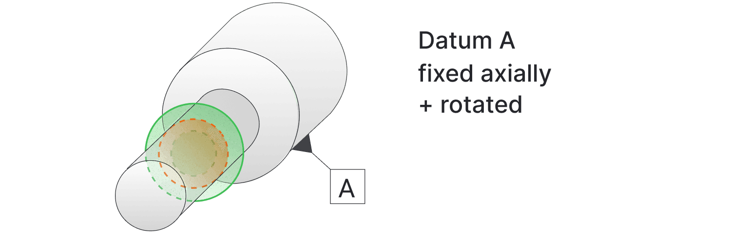
- Definition: Runout controls the variance of a surface or feature at individual cross-sections as the part rotates 360 degrees around a datum axis.
- Application: It is measured at each circular cross-section perpendicular to the axis of rotation.
- Use Case: Useful when controlling roundness, concentricity, and surface variations at specific points along the length of a feature or edge of disc.
Total Runout
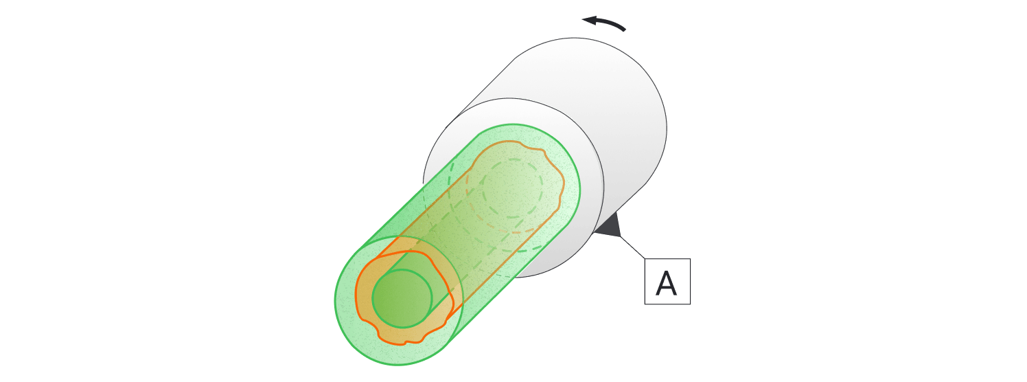
- Definition: Total runout controls the cumulative variation of a surface or feature along its entire length as the part rotates around a datum axis.
- Application: It is measured along the entire surface parallel to the datum axis, considering both radial and axial deviations.
- Use Case: Ideal for controlling straightness, taper, and surface profile over the entire length of a rotating part.
3Understanding Runout
Runout ensures that at any given cross-section perpendicular to the datum axis, the measured surface does not deviate beyond the specified tolerance when the part is rotated 360 degrees.
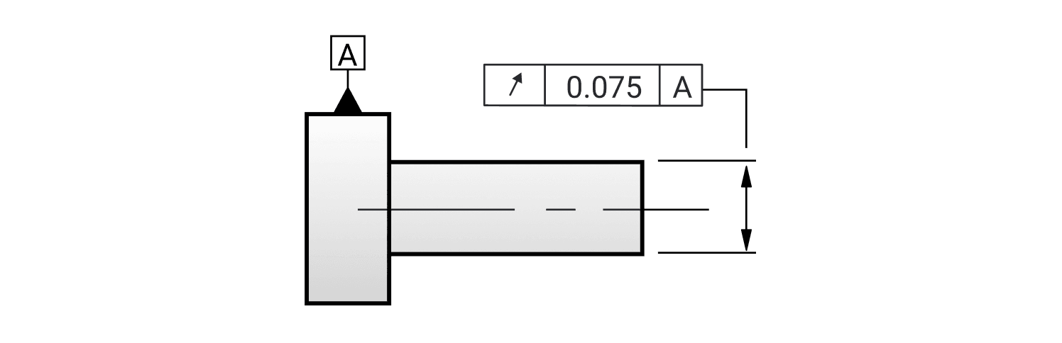
- Tolerance Zone: A two-dimensional circular zone perpendicular to the datum axis within which all measured points of the surface must lie during rotation.
- Controls:
- Circularity (roundness) at each cross-section
- Wobble or eccentricity relative to the datum axis
- Example: In a rotating shaft, runout can control the roundness of bearing surfaces at specific points, ensuring minimal vibration during operation.
4Understanding Total Runout
Total Runout provides a more stringent control by ensuring that the entire surface of a feature remains within the specified tolerance zone when the part rotates.
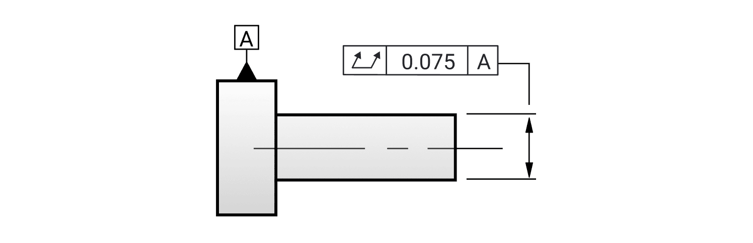
- Tolerance Zone: A three-dimensional zone encompassing the entire surface, within which all points must remain during rotation.
- Controls:
- Cylindricity (combination of roundness and straightness)
- Surface variations along the length, including taper and profile
- Wobble and axial deviations
- Example: For a precision spindle in machinery, total runout ensures that the entire length of the spindle is uniform and balanced, preventing uneven wear and maintaining accuracy.
5Applying Runout Tolerances
Feature Control Frame for Runout:
- Symbol: The runout symbol (regular or total) is placed in the feature control frame.
- Tolerance Value: Specifies the allowable deviation (e.g., 0.075 mm).
- Datum Reference: Runout tolerances always reference a datum axis, typically derived from a datum feature like a bore or shaft centerline.
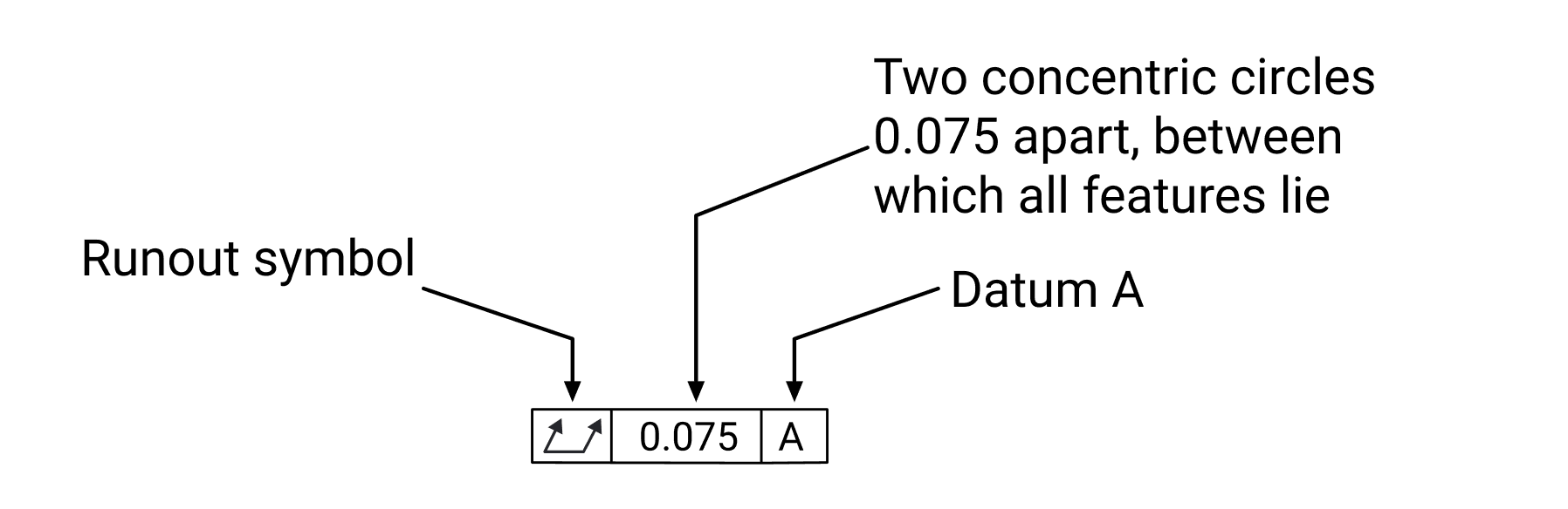
Interpretation:
- The surface must not deviate more than 0.075 mm in runout relative to datum axis A.
6Inspection of Runout
Measuring Runout:

- Setup: Mount the part on a spindle or fixture that aligns with the datum axis (A).
- Instrumentation: Position a dial indicator perpendicular to the surface at the specified cross-section.
- Procedure: Rotate the part 360 degrees and record the Total Indicator Reading (TIR).
- Acceptance: The TIR must not exceed the specified runout tolerance.
Measuring Total Runout:

- Setup: Similar to runout but with the dial indicator capable of moving along the length of the feature.
- Instrumentation: Use a dial indicator or probe that can traverse the entire surface.
- Procedure: Rotate the part and move the indicator along the feature, recording deviations.
- Acceptance: Ensure that the combined radial and axial deviations do not exceed the total runout tolerance.
7When to Use Runout Tolerances
- Runout: Use when you need to control roundness and wobble at specific cross-sectional areas but are less concerned with variations along the length.
- Total Runout: Use when controlling the entire surface is critical, such as in high-precision applications where both form and orientation over the whole length affect functionality.
- Ensures Rotational Balance: Minimizes vibration and noise in rotating components, leading to smoother operation.
- Improves Component Life: Reduces wear by ensuring uniform contact surfaces, enhancing the longevity of parts.
- Enhances Performance: Critical for applications requiring high rotational speeds and precision.
- Facilitates Quality Control: Provides clear, quantifiable criteria for inspection and acceptance of parts.
8Relationship with Other GD&T Controls
- Concentricity: Runout is often preferred over concentricity because it is easier to measure and directly relates to the functional aspects of the part. Concentricity was removed from the Y14.5-2018 standard to reduce misinterpretation during inspection.
- Cylindricity: Total runout can control cylindricity, but it also considers the part’s orientation and location relative to a datum axis. Cylindricity was removed from the Y14.5-2018 standard to reduce misinterpretation during inspection.
- Profile Tolerances: Runout can be used in conjunction with profile tolerances to provide comprehensive control over complex surfaces.
9Tips for Using Runout Tolerances
- Select the Appropriate Type: Choose runout for controlling features at specific sections and total runout for entire surfaces.
- Define Accurate Datums: Clearly specify datum features that are practical for manufacturing and inspection setups.
- Balance Precision and Manufacturability: Specify tolerances that are tight enough to ensure functionality but reasonable for manufacturing capabilities.
- Plan for Inspection: Ensure that the necessary equipment and procedures are available to verify the runout tolerances specified.
Runout tolerances are essential tools in GD&T for controlling the functional aspects of rotating parts. By applying regular or total runout appropriately, engineers can ensure that components operate smoothly, efficiently, and with minimal maintenance issues. Understanding how to specify and measure runout is crucial for the design and manufacture of high-quality mechanical systems.
Ready to enhance the precision of your rotating components? Mastering runout tolerances in GD&T can significantly improve the performance and reliability of your designs. If you have questions or need assistance with applying runout tolerances, feel free to reach out, we’re here to support your engineering success!
Get the next one.
New notes go out to the Drafter newsletter. A free account signs you up, and opens the calculators and cheat sheets in the toolbox while you wait.
Create a free accountKeep reading
 GD&TAngularityAngularity in GD&T is a symbol that defines the orientation of one feature relative to another at a specified angle within a 3D tolerance zone.Surface control shown to left. Angularity can also apply to a FOS where the derived median plane or line is controlled.
 GD&TParallelismParallelism in GD&T ensures that a referenced feature maintains a parallel orientation to a specified datum surface or line within a 3D tolerance zone.
 GD&TStraightnessStraightness is one of the most fundamental form tolerances. It is used to ensure that a feature, such as a surface or an axis, conforms to a specific linear path without deviations. Straightness is crucial for parts where linear precision is vital for fit, function, and performance.