

MBD
The future is model-based.
Drafter puts the definition on the model. The same read of the geometry that produces a drawing attaches the datums, tolerances and notes to the faces and features they control. You still get the sheet.

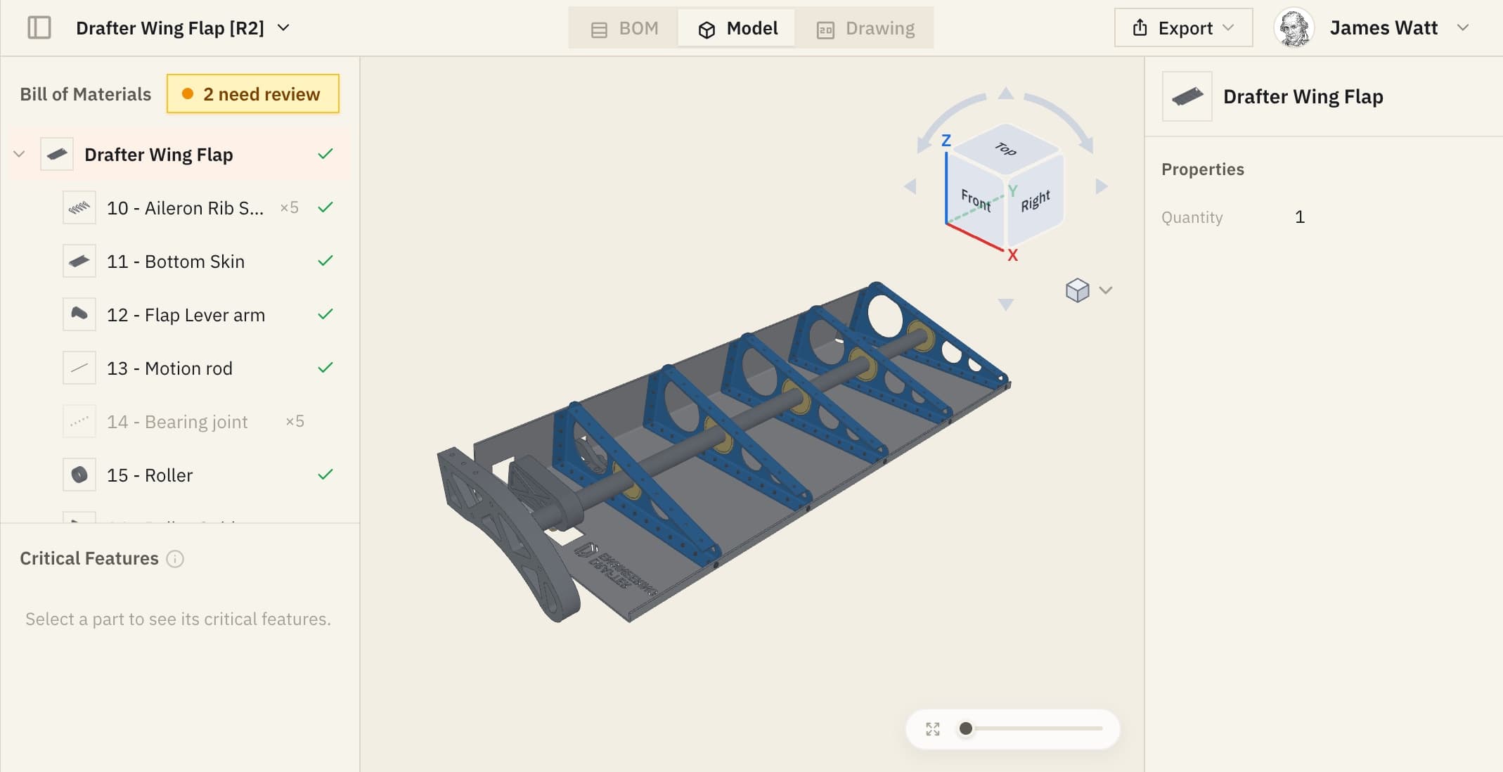
The tolerance sits on the face it controls.
On a drawing, a position tolerance points at a hole, and someone downstream has to work out which one. Here every callout is attached to the face it controls, on all six sides of the part.
One workflow, both outputs.
MBD puts the tolerances, datums and notes on the model itself, so machining, inspection and suppliers all work from one source instead of re-reading a drawing. Drafter gets you there without a second workflow: one read of the geometry produces the model definition and the 2D drawing together, so the two always agree.
See Assembly
Capabilities
What gets attached.
Controls on the features
Feature control frames attach to the faces and features they govern, with the datum references that define them, rather than sitting in a note somebody has to associate with the right hole.
ASME Y14.41 and Y14.47
The standards model-based definition is written to: Y14.41 for how annotations are applied to a 3D model, and Y14.47 for how the model's data is organized. The callouts themselves still mean exactly what ASME Y14.5 says.
In the CAD you already run
The annotations live in the model in SolidWorks and Siemens NX, so the people downstream open the file they always open rather than learning a viewer.


The sheet and the model agree
Both come out of one read of the geometry, so there is no second definition to maintain and no drift between what the drawing says and what the model carries.
Change it and re-run
A design change regenerates the definition rather than being re-applied by hand, which is where a hand-maintained MBD scheme usually starts falling behind the model.
Your conventions, either way
Your title block, your sheet sizes and your tolerancing defaults apply whether the definition is printed on a sheet, attached to the model, or both.
The definition goes where the part goes.
Turn it. The flatness callout, the datums and the position tolerance are not drawn beside this part, they are attached to it, and they move with it. This is NIST's public reference model for model-based definition, in STEP AP242, drawn straight out of the file. Your own models never leave your workspace.
How we handle controlled programsQuestions
What teams ask about MBD.
- Does this replace the drawing?
- For most teams, no, and we will not pretend otherwise. Your shop, your suppliers and your quality group will keep asking for a sheet for years. MBD earns its place where a downstream process reads the model directly: CAM, CMM programming, inspection planning. Drafter gives you both from one read, so adopting it is not a bet.
- Which CAD does it work in?
- SolidWorks and Siemens NX, where Drafter runs as a native add-in. The annotations live in the model itself rather than in a separate file alongside it.
- Does the definition survive when the model leaves our CAD?
- That depends entirely on what you are handing it to, and it is a question with a real answer rather than a marketing one. Tell us the downstream you need to feed and we will tell you plainly what carries into it and what does not.
- Is MBD a separate product from Assembly?
- It is the same engine with a different output. We list it on its own because teams are told to go and find model-based definition by name, and they should not have to read a feature list to learn that the answer is yes.
- Do we have to move the whole company onto it?
- No. A part can carry model annotations, a drawing, or both, and that choice can be made per program. Teams generally start where the pain is, which is usually inspection.
- Who checks the annotations before they are applied?
- Your engineer, the same as on a sheet. Drafter proposes the datums and the tolerances from the geometry, and nothing is attached until somebody with their name on the part accepts it.
The rest of Drafter
Four more products, on the same models.
Assembly
Send the assembly and get a dimensioned, toleranced sheet back for every part in it, to ASME Y14.5-2018 and in your title block.
See AssemblyBlueprints
Set up a part you draw constantly once, then get its drawing back on one click from inside your CAD, already the way your shop expects it.
See BlueprintsNotes
Your standard notes, plus the ones this particular part earns from its material, its process and its features, placed as soon as the drawing exists.
See NotesRedliner
Upload any drawing, ours or a supplier's, and get it checked against ASME Y14.5 and what the floor actually needs, with the rule behind every finding.
See the Redliner