What Exactly is GD&T Flatness?
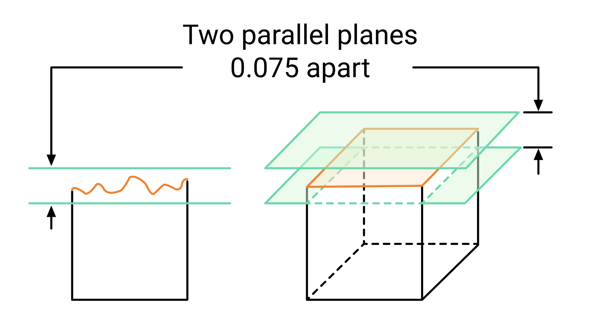
Flatness in GD&T is all about making sure that a surface isn’t wavy or uneven when it should be lying between two parallel planes as seen in the image above. Essentially, a surface must lie entirely within these two planes, which are separated by a specified tolerance zone. Think of this tolerance zone as a boundary within which the entire surface must remain. If any part of the surface extends beyond this boundary, it doesn’t meet the flatness requirement.
Flatness is a form control, meaning it concerns only the shape of the surface itself, independent of other features. Unlike position tolerances, which depend on a datum reference frame (DRF), flatness is purely about the surface’s geometry. Whether you’re working with machined parts, castings, or any component requiring precision, flatness is an essential part of the dimensions and tolerances that ensure your project’s success.
Applying GD&T Flatness in Engineering Drawings
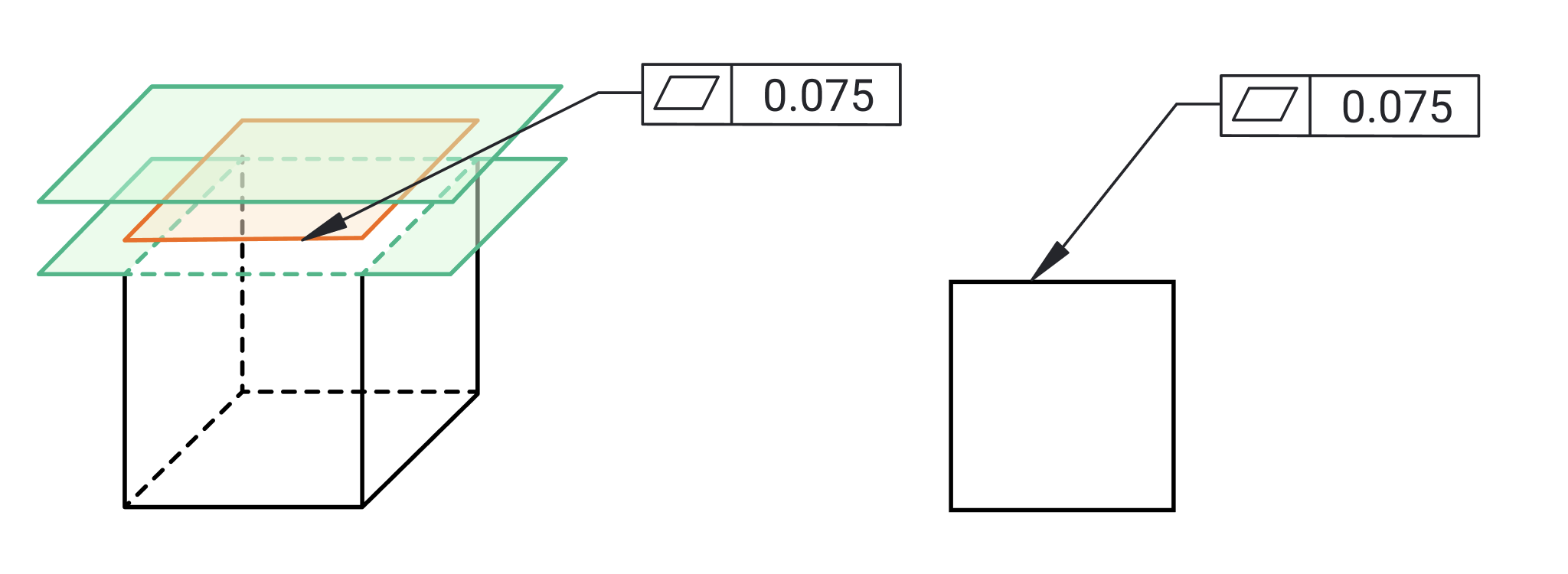

Once you’ve measured the flatness of your surface, it’s time to document it in your engineering drawings. Here’s how to do it effectively:
- Choosing the Right Tolerance: Selecting an appropriate flatness tolerance is crucial. If the tolerance is too tight, manufacturing the part may become challenging or expensive. If it’s too loose, the part might not function as required. It’s important to balance the flatness requirement with the functional needs of the part and the capabilities of your manufacturing process.Flatness tolerance is typically expressed in millimeters or inches, depending on your measurement system. The key is to select a tolerance that aligns with the part’s intended function and the capabilities of your manufacturing process. For example, if a surface is critical for sealing, like in a gasket application, a tighter flatness tolerance is necessary. But if the surface isn’t as critical, you can afford to be more lenient, which can save time and cost in production.
- Using the Feature Control Frame: In your engineering drawing, the flatness requirement is specified using a feature control frame. This frame includes the flatness symbol and the tolerance value. You can also indicate material conditions like Maximum Material Condition (MMC) or Least Material Condition (LMC) in the feature control frame.The feature control frame is a critical element in communicating flatness requirements. In addition to the flatness symbol and tolerance, you can also include additional geometric tolerances if needed. For instance, if the flatness of a surface is critical when the part is at its maximum material condition, you can specify this in the feature control frame. This tells the machinist or inspector that they need to verify flatness when the part is at its largest allowable size, ensuring that the part will still function properly even in the worst-case scenario.
- Material Conditions (MMC and LMC): Material conditions, such as MMC and LMC, ensure flatness requirements are met at the part’s extreme material conditions, which is essential for maintaining proper fit and performance in high-precision assemblies with minimal clearance.
Example
Consider the glass screen of a smartphone. During manufacturing, if the surface of the glass isn’t flat within the specified flatness tolerance zone, it won't align perfectly with the frame. This tolerance zone is defined on the engineering drawing using a flatness control in the feature control frame, specifying that the glass surface must lie between two parallel planes. If the surface deviates beyond these planes—outside the tolerance zone—it could lead to issues like improper sealing, allowing dust or moisture to enter the device. By applying a flatness control in the drawing, the manufacturer ensures that every point on the surface stays within the allowed tolerance, guaranteeing both functional performance, such as touch sensitivity, and the part's proper fit during assembly.
The Importance of Flatness
Imagine assembling a product and discovering that the parts don’t fit together because one of them has an uneven surface. That’s where flatness becomes crucial. A perfectly flat surface ensures that parts join together seamlessly, preventing gaps, misalignment, or uneven wear.
In industries like aerospace and automotive, where precision is paramount, controlling flatness is essential. Flatness isn’t just about making things fit better—it’s also about ensuring longevity and performance. In high-precision environments, even minor deviations in flatness can lead to increased wear, fatigue, and, ultimately, part failure. A surface that isn’t flat can cause uneven pressure distribution, leading to stress concentrations that weren’t accounted for in the design. Over time, this could result in cracks, material failures, or even more severe breakdowns.
How to Measure Flatness
Now that we’ve established why flatness is essential, let’s talk about how you actually measure it. Measuring flatness requires precision, but with the right tools, it’s straightforward.
- `Surface Plates and Height Gauges: These are the most basic tools for measuring flatness. A surface plate provides a flat reference, and a height gauge measures deviations from this reference. It’s a simple and effective method, but it’s best suited for smaller surfaces. Surface plates, often made from granite, are incredibly flat and stable, providing a reliable reference point.To measure flatness, you place your part on the surface plate and use a height gauge to measure various points on the surface. If the readings fall within your flatness tolerance zone, the surface meets the flatness requirement. However, this method has its limitations. It’s more suitable for smaller parts or surfaces and might not provide the necessary resolution for high-precision applications.
- Coordinate Measuring Machines (CMM): For more complex or larger surfaces, CMMs are ideal. These machines use probes to gather precise data points on your surface, which are then compared to a reference plane. This method provides an accurate measurement of flatness, making it suitable for industries where precision is critical.CMMs can handle complex surfaces, irregular shapes, and high precision requirements. By taking multiple points across the surface, the CMM can calculate the best-fit plane and determine how much the actual surface deviates from this ideal. The result is a highly accurate flatness measurement, crucial in industries like aerospace or medical device manufacturing, where precision is paramount.
- Optical Methods: Optical methods like laser scanning or interferometry offer non-contact, highly accurate measurements of flatness. These methods are particularly useful for delicate surfaces or large parts where traditional contact methods might not be practical.Optical methods are especially useful when dealing with surfaces that are either too delicate for contact methods or too large to measure efficiently with traditional tools. Laser scanning, for instance, can quickly capture the topography of a surface and provide a detailed map of its flatness. Interferometry, on the other hand, uses the interference of light waves to measure surface deviations at the nanometer scale. These methods are especially useful in industries like semiconductor manufacturing, where even the slightest imperfection can affect performance.
Challenges in Controlling Flatness
While flatness might seem straightforward, there are several challenges that engineers need to consider:
- Surface Finish: The surface finish can impact flatness measurements. A surface may appear flat over a large area but have small-scale roughness that falls outside the flatness tolerance. It’s important to account for surface finish when specifying and measuring flatness.Surface finish and flatness are related but distinct concepts. A surface can be flat over a large scale but still have a rough texture, which could interfere with its performance in certain applications. For example, in sealing surfaces, a rough finish could lead to leaks even if the surface is technically flat. That’s why it’s essential to specify both flatness and surface finish in your engineering drawings, ensuring that the part meets all the necessary criteria.
- Thermal Expansion: Materials expand and contract with temperature changes, which can affect flatness measurements. To get accurate readings, measurements should be taken in a temperature-controlled environment, or adjustments should be made based on the material’s coefficient of thermal expansion.Thermal expansion can significantly impact flatness, especially in materials with high thermal coefficients. Even a small temperature change can cause significant deviations in flatness, particularly in large parts. To mitigate this, it’s important to conduct measurements in a temperature-controlled environment or make adjustments based on the material’s thermal expansion properties.
- Manufacturing Processes: Processes like machining, welding, or heat treatment can introduce stresses that warp a part, affecting its flatness. Implementing proper process controls and stress relief techniques is crucial to maintaining flatness.Manufacturing processes can introduce residual stresses into a part, leading to warping and changes in flatness. For example, machining can remove material unevenly, causing the part to distort. Welding can introduce heat, causing the material to expand and contract unevenly. Heat treatment can alter the material’s structure, leading to warping. To address these challenges, it’s essential to implement process controls and stress relief techniques, such as controlled cooling or post-process annealing.
Summary
- GD&T Flatness: Ensures a surface lies within two parallel planes, independent of other features, to maintain part functionality and precision.
- Importance: Critical for fitting parts together, ensuring proper sealing, load distribution, and preventing stress concentrations that could lead to failure.
- Measurement Methods:
- Surface Plates & Height Gauges: Simple, effective for smaller parts.
- Coordinate Measuring Machines (CMM): High precision, suitable for complex surfaces.
- Optical Methods: Non-contact, ideal for delicate or large surfaces.
- Application in Drawings:
- Choose appropriate flatness tolerance.
- Use a feature control frame to specify flatness, including material conditions like MMC/LMC.
- Challenges:
- Surface Finish: Can affect flatness; consider both in specifications.
- Thermal Expansion: Requires controlled measurement environments or adjustments.
- Manufacturing Stresses: Processes like machining or welding can warp parts; use stress relief techniques.
- Best Practices:
- Design with manufacturability in mind.
- Implement process controls and regularly calibrate measurement tools.
- Educate teams on the importance of flatness and its measurement.
Have questions? Contact support@drafterinc.com


